
ID49
- Chip part number
- NCF2951 / NCF2952 / NCF2961
- Manufacturer
- NXP Semiconductors (formerly Philips)
- Protocol
- Hitag Pro (Hitag 3)
- Integration
- Integrated on key PCB
- Cloneable
- NO (Must be programmed via OBD or Bench module connection)
- Clone blank
- N/A
BMW · 2013 – 2021
Vehicle identification reference. Always confirm the actual module and market specification.
Reviewed reference. Confirm the actual module and market before working. Parts and specifications may vary within the same model year.
For a BMW configuration or replacement-module setup request, review BMW replacement-module coding and configuration. Coding is separate from key authorization and depends on the actual installed module.
Locate the controller
FEM passenger footwell
1. Remove the plastic trim: Carefully pry off the door sill trim and the plastic kick panel in the passenger footwell.
2. Peel back carpet: Pull the carpet away from the side wall/A-pillar area to reveal the metal bracket holding the module.
3. Identify by Fuses: The module is easily identified because it doubles as a fuse box with dozens of fuses plugged directly into its face
Pro Tip: If you are removing this because of electrical glitches (like car not recognising key, windows and lights acting up etc), check the connectors for corrosion or water. A common failure point is water leaking from clogged sunroof drains directly onto this module.
Visual reference
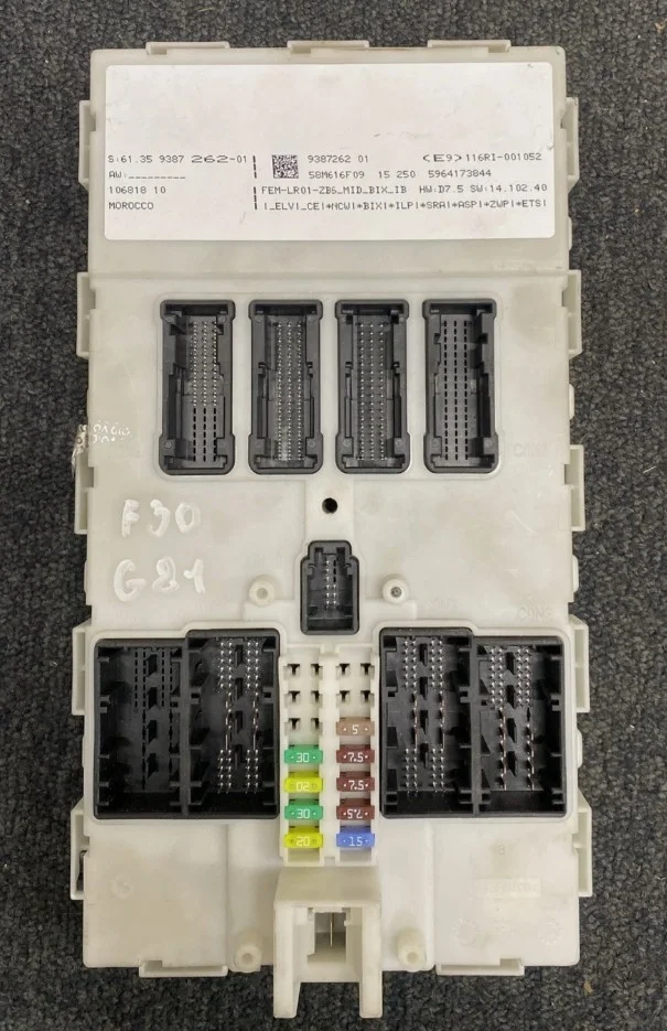
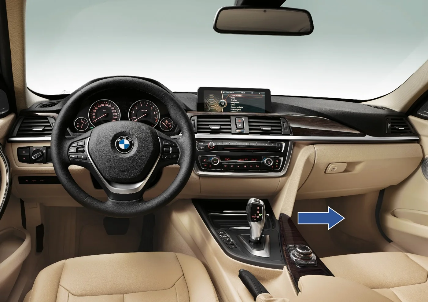
Open a photo for the full-size reference. Module position and hardware may differ by market or specification.
On the job
Medium • 30–60 min • Preprocess EEPROM on bench then OBD add key
FEM/BDC preprocess (EEPROM read) required before OBD programming
✅ AVDI BN016 – many FEM/BDC via OBD after preprocess
✅ Autel IM608/IM508S, VVDI2/Prog, CGDI – supported (preprocess needed)
⚠️ OBDStar, Xtool, Smart Pro, Launch – partial; success varies, BDC2 weaker
⚠️ Lonsdor K518 – supports FEM/BDC unlock & OBD after preprocess
Hard • 1.5–3 h • Bench preprocess (95128/95256) + OBD programming
Bench preprocess/unlock FEM/BDC (read 95128/95256 & D-FLASH), then OBD to finish
✅ Autel IM608, VVDI2/Prog, AVDI BN016, CGDI – supported
⚠️ OBDStar, Xtool, Smart Pro, Launch – limited on BDC/BDC2
⚠️ Lonsdor – partial; case-dependent
FEM: 95128/95256; BDC/BDC2: 95256. Module in passenger footwell A‑pillar
✅ VVDI Prog, CG Pro, AVDI, Autel, CGDI – supported
⚠️ OBDStar, Xtool, Smart Pro, Launch – partial
⚠️ Lonsdor – partial
Professional reference
BMW EWS3 AKL Procedure Guide
OBD Programming: EWS3 does NOT support All Keys Lost programming via OBD. Bench work is mandatory.
Module Removal Required: You must remove the EWS3 module from the vehicle and read data on the bench.
MCU Types:
0D46J - Can be read via K-line adapter (safer method)
2D47J - Requires MCU adapter, risk of memory erasure during read
Vehicle Coverage: BMW E36, E38, E39, E46, E53 (X5), Z4, Mini Cooper, Range Rover (2001-2006)
Transponder Chip: PCF7935 or PCF7930/PCF7931
GENERAL AKL PROCEDURE (All Tools)
1. Verify EWS3 System
Check production year (2001-2006)
Locate EWS3 module (typically behind glove box or under dash)
Note module part number
2. Remove EWS3 Module
Disconnect battery negative terminal
Remove module mounting screws
Disconnect connector carefully
Document connector orientation
3. Identify MCU Type
Open EWS3 module housing
Locate processor chip
Read mask number on chip (0D46J or 2D47J)
For 0D46J (Recommended Method):
Connect via K-line adapter to module connector
No MCU removal required
Read EEPROM data
Always read 2-3 times and verify consistency
For 2D47J (Caution Required):
Use dedicated 2D47J adapter
Never attempt K-line read on 2D47J (will erase memory)
Provide external 12V power
Read carefully - erasure risk exists
4. Save Original Dump
Create backup of original EEPROM data
Verify file integrity
Store securely for future reference
5. Analyze EEPROM Data
Load dump into key programming software
Verify VIN matches vehicle
Check existing key positions (typically positions 1-8)
Confirm password data is present
6. Prepare Dealer Key
Select unused key position (e.g., Position 4 or 5)
Place blank PCF7935 transponder in programming coil
Execute "Make Dealer Key" or equivalent function
Verify successful programming
7. Cut Key Blade
Use key code from EEPROM or decode existing key
Cut physical blade to match
8. Reinstall EWS3 Module
Reconnect module to vehicle
Secure mounting
Reconnect battery
9. Test Key
Insert programmed key
Turn to position II (ignition on)
Verify immobilizer light behavior
Attempt engine start
Confirm successful start
VVDI2 (Xhorse)
Required Hardware:
VVDI2 Commander
BMW Function License
VVDI Prog with EWS3 adapter OR external programmer
Procedure:
Connect EWS3 to VVDI Prog using EWS3 adapter
Launch VVDI2 software → BMW Programmer
Select "Read EWS3 EEPROM"
Save dump file to PC
Go to "Get Key Info" → "Lost All Key"
Place blank PCF7935 in coil
Select key position → "Prepare dealer key with programmer"
Confirm key programming successful
Notes: VVDI2 can read via programmer or external EEPROM dump. For 0D46J, K-line reading is supported. For 2D47J, use adapter method only.
Autel IM608 / IM508
Required Hardware:
Autel IM608 or IM508 tablet
XP400 Pro key programmer
APB114 EWS3 adapter board (part of IMKPA accessories)
12V power supply
Procedure:
Remove EWS3 from vehicle
Connect APB114 adapter to EWS3
Connect adapter to XP400 Pro
Provide external 12V power
Navigate: IMMO → BMW → EWS → EWS3 K-line 0D46J
Select "Read"
Save EEPROM dump
Select "Key Learning" → "All Keys Lost"
Follow on-screen prompts
Insert blank transponder in XP400 Pro
Select key position and write key
Verify programming complete
Notes: IM608/IM508 requires APB114 adapter for EWS3. Connection diagram displayed on screen. For 2D47J, adapter method required.
Xtool X100 Pad3 / Pad Elite
Required Hardware:
X100 Pad3 or Pad Elite tablet
KC100 key programmer adapter
External EEPROM programmer (AK90+, Xprog, or similar)
Procedure:
Read EWS3 D-FLASH/EEPROM with external programmer
Save dump file to tablet via USB or cloud
Connect X100 Pad3 to vehicle via OBD (for coding only)
Navigate: Immobilizer → BMW → EWS
Select "Read Keys Info" (if needed)
Connect KC100 adapter
Place blank PCF7935/PCF7930 in KC100 coil
Select "Write Start Key"
Load saved EEPROM dump file
Choose unused key position
Execute key writing
Verify dealer key generation success
Notes: X100 Pad3 does NOT read EWS3 directly - external programmer required first. KC100 used only for key writing. Not OBD-capable for EWS3 reading.
OBDSTAR X300 DP Plus
Required Hardware:
X300 DP Plus tablet (C Package recommended)
P001 programmer with adapters
Procedure:
Remove EWS3 module
Connect appropriate adapter for 0D46J or 2D47J
Navigate: IMMO → BMW → EWS
Read EEPROM data
Save dump file
Select key programming function
Place blank transponder in coil
Follow guided procedure
Write key to selected position
Notes: X300 DP Plus has limited EWS3 support compared to newer CAS systems. Verify specific EWS3 capability in latest software version. P001 programmer kit required.
Required Hardware:
AVDI interface with active subscription
ZN055 ABPROG EWS3 adapter
ABPROG programmer
ZN002 or ZN003 PROTAG key programmer
Procedure:
Remove EWS3 module from vehicle
Open EWS3 housing to access PCB
Connect ABPROG with ZN055 EWS3 adapter
Launch ABRITES software → BMW
Select EWS3 programming function
Read EEPROM data via K-line (0D46J) or adapter (2D47J)
Save data file
Navigate to key programming
Use PROTAG to prepare PCF7935 transponders
Program keys to selected positions
Verify programming successful
Notes: ABRITES requires annual subscription. PROTAG separately prepares transponders. ZN055 adapter connects ABPROG to EWS3 module. Professional-grade system with extensive BMW coverage.
Smart Pro (Advanced Diagnostics)
Required Hardware:
Smart Pro tablet
Smart Aerial
ADC2000 cable (for BMW connection)
Tokens or software modules
Note: Smart Pro primarily focuses on CAS2/CAS3/CAS3+ systems for BMW. EWS3 support is limited. For EWS3 AKL, consider using dedicated EWS programmers in conjunction with Smart Pro's CAS capabilities. Verify current EWS3 coverage with manufacturer before attempting procedure.
Xhorse Key Tool Plus
Required Hardware:
Key Tool Plus tablet
VVDI Mini Prog or VVDI Prog
XDNP50 EWS3 adapter (for Mini Prog) OR VVDI Prog EWS3 adapter
Blank PCF7935 transponders
Procedure:
Remove EWS3 from vehicle
Connect EWS3 to Mini Prog using XDNP50 adapter
Read EEPROM and save dump
Upload file to Key Tool Plus (via USB or cloud)
On Key Tool Plus: Immo Data Tool → Europe → BMW → EWS3
Load saved dump file
Review key information and positions
Select unused key position (Position 4, 5, etc.)
Place blank PCF7935 in Key Tool Plus coil
Tap "Prepare Dealer Key"
Select chip type: PCF7930/PCF7931/PCF7935
Wait for "Dealer key success" confirmation
Cut blade using Key Tool Plus or separate machine
Notes: Key Tool Plus combines functions of VVDI2, Key Tool Max, and programming capabilities. Mini Prog required for EWS3 reading. Can also work with AK90+ or other external programmers. Files can be transferred via USB or cloud storage.
EWS3 Module Specifications
Module Types:
Hardware versions: HW1, HW2, HW3
Software versions: SW1 through SW8
Processor masks: 0D46J (newer), 2D47J (older)
Key Positions: EWS3 supports up to 8 keys (positions 0-7)
Password System: Internal password for key synchronization and DME communication
Common Issues & Solutions
Problem: Failed to read 2D47J
Solution: Ensure proper adapter connection, provide stable 12V power, lift specific pins if required
Problem: "Wrong changing code" error
Solution: EWS-key synchronization issue. May require editing EWS file or programming new key with correct password
Problem: Module erased during read
Solution: If 2D47J memory lost, use EWS Factory Reset function and rebuild with DME data
Problem: Car cranks but won't start
Solution: Check EWS-DME synchronization, verify password matching between modules
Safety Precautions
Always read EEPROM data 2-3 times and verify consistency
Never write corrupted or mismatched data back to EWS3
Keep original dumps stored securely
For 2D47J, never attempt K-line reading - use proper adapter
Ensure stable power supply during all operations
Verify VIN matches before programming keys
Professional Tips
Document all connector orientations with photos before removal
Label all saved files clearly with VIN and date
Test programmed keys before final reassembly
Keep backup of working dump files
Consider DME synchronization requirements for full functionality
For questions regarding specific tool compatibility or procedure variations, consult your tool manufacturer's latest documentation or technical support. BMW immobilizer systems are continuously evolving, and software updates may add new capabilities or change existing procedures.
This guide is for professional automotive locksmiths and technicians with appropriate training and equipment.
BMW CAS3/CAS3+ All Keys Lost (AKL) - Quick Professional Guide
⚠️ CRITICAL SAFETY WARNINGS
POWER SUPPLY MANDATORY: Use 12V battery maintainer at 13.5-14.2V throughout entire procedure. 85% of CAS failures are from voltage drops.
NEVER INTERRUPT POWER: Power loss during programming permanently damages CAS ($400-1,200 repair).
BACKUP FIRST: Always create CAS backup before starting - your only recovery option.
Vehicle Identification
CAS3 (2006-2009 E-Series)
Processor: 9S12XDP512 / 9S12HZ256
Models: E60, E61, E70, E71, E81, E82, E87, E88, E90, E91, E92, E93
ISN: Optional for most tools
CAS3+ (2009-2012 E-Series)
Processor: 9S12XEP100
Models: Late E60/E90 facelift, E84 X1
ISN: Recommended but often not required
Required Equipment
Programming tool (VVDI2, Xhorse Key Tool Plus, Autel IM608, Lonsdor K518, OBDSTAR G3)
12V battery maintainer (3A minimum)
Blank BMW key (ID46/PCF7942 for CAS3, PCF7945/Hitag2 for CAS3+)
Key cutting equipment
Correct frequency: 315MHz (USA), 433/868MHz (Europe)
Using XHORSE Key Tool Plus
Step 1: Connect & Setup (5 min)
Connect battery maintainer - verify 13.5V+
Connect Key Tool Plus to OBD port
Tap "IMMO Programming" → "Europe" → "BMW"
Select "Automatically diagnose models"
Verify CAS3/CAS3+ detected correctly
Step 2: Read Key Information (3 min)
Tap "Generate keys via OBD"
Tap "Read key information"
If connection fails: Press brake pedal 3x or activate hazards
Note available key positions (shows "FFFFFFFF Enable")
Step 3: Create Backup (5 min) ⚠️ MANDATORY
Tap "Backup CAS Data"
Enter filename: VIN_DATE_CAS3_BACKUP
Wait for completion (2-4 minutes)
Verify backup saved successfully
Export to cloud storage/email
Step 4: Unlock CAS (5 min) ⚠️ CRITICAL
Verify battery maintainer shows 13.5V+
Tap "Unlock CAS3/CAS3+"
Confirm backup created
Tap "Start Unlock"
DO NOT TOUCH ANYTHING - process takes 3-7 minutes
Wait for "Unlock Successful" message
PHOTOGRAPH security keys displayed (write them down)
Step 5: Program Key (8 min)
Prepare blank key (correct chip, blade cut)
Tap "Prepare dealer key with ignition switch"
Select empty key position (shows "FFFFFFFF")
Select "Unencrypted" version
Position key:
Keyless: Place near START/STOP button
Traditional: Insert in ignition (OFF position)
Tap "Start Programming"
Wait 5-8 minutes for completion
Success message: "Key learn success"
Step 6: Verify & Test (5 min)
Tap "Read key information" - verify position now shows "Enable"
Remove key and test remote (lock/unlock)
Insert key and turn ignition ON (don't start yet)
Wait 15 seconds (critical for sync)
Start engine - should crank immediately
Let run 30 seconds
Test all functions (remote, trunk, engine start/stop)
Step 7: Synchronize Remote (if needed)
Start engine and drive forward 30+ seconds
Press lock/unlock while driving
Or use Key Tool Plus "Synchronize Keys" function
Using VVDI2
Step 1: Connect & Setup (5 min)
Connect battery maintainer - verify 13.5V+
Connect VVDI2 to OBD and laptop via USB
Launch VVDI2 Commander software
Click "BMW" → "CAS3/CAS3+" → "OBD Mode"
Click "Read CAS Info" to verify detection
Step 2: Backup CAS Data (8 min) ⚠️ MANDATORY
Click "Create Backup" or "Read CAS Data"
Wait for reading (4-7 minutes)
Save as: VIN_DATE_CAS3_BACKUP.bin
Click "Verify Backup" to confirm integrity
Copy backup to multiple locations
Step 3: Unlock CAS (10 min) ⚠️ CRITICAL
Verify laptop on AC power, battery maintainer at 13.5V+
Click "Unlock CAS3/CAS3+"
Read all warnings carefully
Confirm backup created
Click "Start Unlock"
DO NOT INTERRUPT - takes 5-10 minutes
Process stages:
Connection → Authentication → Reading → Flash Update (2-4 min - most critical) → Verification
Wait for "Unlock Successful" message
SCREENSHOT security keys displayed
Step 4: Program Key (12 min)
Prepare blank key (correct chip, blade cut)
Click "Program Dealer Key"
Select empty position (shows "FFFFFFFF" or "Empty")
Choose "Standard Mode" (or "Secure Mode" if using ISN)
Position key:
Keyless: Near emergency coil
Traditional: Insert in ignition (OFF)
Click "Start Programming"
Wait for stages:
Key Detection → Calculate Data → Write CAS → Write Chip → Verify
Total time: 8-12 minutes
Success message appears
Step 5: Test Key (5 min)
Remove key and test remote functions
Insert key, turn ignition ON
Wait 15 seconds before starting
Start engine - should crank immediately
Let idle 30 seconds
Drive 30+ seconds if remote doesn't work (auto-sync)
Using Autel IM608
Step 1: Connect (5 min)
Connect battery maintainer at 13.5V+
Connect IM608 to OBD
Tap "IMMO" → "BMW" → Select year/model → "CAS3/CAS3+"
Step 2: Backup & Unlock (10 min)
Tap "All Keys Lost"
Tap "Read CAS Data" - auto-saves backup (5-12 min)
Tap "Continue" to unlock
DO NOT INTERRUPT during flash update
Wait for "Unlock Successful"
Step 3: Program Key (8 min)
Tap "Program Key"
Select empty key slot
Insert key or use XP400 simulator
Follow on-screen prompts
Wait for completion
Test all functions
Using Lonsdor K518
Step 1: Connect (5 min)
Connect battery maintainer at 13.5V+
Connect K518 to OBD
Select "Immobilizer" → "BMW" → "CAS3/CAS3+"
Step 2: Backup & Unlock (8 min)
Select "All Keys Lost"
K518 reads and backs up CAS data automatically
Follow prompts for unlock procedure
Wait for completion (don't interrupt)
Step 3: Program Key (8 min)
Select "Add Key"
Choose empty position
Insert key in K518 card slot or position near vehicle coil
K518 programs automatically
Wait for "Success" message
Test key functions
Using OBDSTAR G3
Step 1: Connect (5 min)
Connect battery maintainer at 13.5V+
Connect OBDSTAR to OBD
Select "Immobilizer" → "BMW" → "CAS3/CAS3+"
Step 2: Backup & Unlock (10 min)
Select "All Keys Lost" function
Device reads CAS and creates backup
Follow unlock prompts
Wait for completion
Step 3: Program Key (8 min)
Select "Add New Key"
Choose key position
Position key as directed
Wait for programming completion
Test all functions
When to Use Bench Method
OBD unlock failed
CAS damaged/unresponsive via OBD
Enhanced security variant
ISN required and must read from DME
CAS Removal (60-90 min)
Location: Bottom left of steering wheel area
Removal Steps:
Disconnect battery negative terminal
Remove dashboard panels to access CAS:
Center LCD screen cover
Right air outlet
Trim panels
AC control panel
Photograph all connectors before removal
Disconnect CAS connectors (press release tabs)
Remove mounting bolts
Extract CAS carefully - place in anti-static bag
Using Lonsdor K518 (Bench Method)
Step 1: Read CAS EEPROM (20 min)
Use VVDI Prog or similar to read CAS EEPROM
Identify chip type (95128/95256)
Connect appropriate adapter
Read EEPROM and save as .BIN file
Save backup: VIN_CAS3_EEPROM.bin
Step 2: Program with K518 (15 min)
Copy EEPROM file to K518 "customfile" folder
On K518: "Immobilizer" → "BMW" → "CAS3/CAS3+"
Select "Make Dealer Key"
Choose imported EEPROM file
Enter ISN if prompted (32-digit hex from DME)
Insert blank key in K518 card slot
K518 programs automatically (2-3 min)
"Generate key success" message appears
Step 3: Reinstall CAS (30 min)
Reconnect all CAS connectors (match photos)
Install mounting bolts
Reassemble dashboard panels
Reconnect battery
Test key: Start engine, wait 15 seconds, test all functions
Using VVDI2 (Bench Method)
Step 1: Connect CAS to Test Platform (10 min)
Place CAS on GODIAG test platform
Connect adapters according to pinout
Connect 12V bench power supply (13.5V)
Connect platform to VVDI2
Launch VVDI2 software
Step 2: Backup & Unlock (15 min)
Select BMW → CAS3/CAS3+ → Bench Mode
Click "Read CAS Data" - save backup
Click "Unlock CAS3/CAS3+"
Wait for completion (safer on bench than in vehicle)
Record security keys displayed
Step 3: Program Key (12 min)
Enter ISN if prompted
Click "Program Dealer Key"
Select key position
Place blank key on test platform coil
Click "Start Programming"
Wait for completion
Test key on platform before reinstalling CAS
Step 4: Reinstall (30 min)
Disconnect bench setup
Reinstall CAS in vehicle (reverse of removal)
Reconnect battery
Test key functions
ISN Reading (If Required)
Most CAS3 systems work WITHOUT ISN
Some CAS3+ variants may require ISN
Try via programming tool
Usually fails on E-series
If successful, ISN displays automatically
Remove DME from vehicle (location varies by model)
Use VVDI Prog + appropriate DME adapter
Read ISN from DME EEPROM (32-digit hex)
Takes 20-30 minutes
Or use professional ISN service ($150-300, 24-48 hrs)
Most CAS3 procedures work fine without ISN
Key will function fully (immobilizer + remote)
Troubleshooting
"Cannot Connect to CAS"
Check battery voltage (must be 12.5V+)
Press brake pedal 3x or activate hazards
Verify OBD cable secure
Try different USB port
"Unlock Failed"
Restore from backup immediately
Check power supply stable at 13.5V+
Update tool software
Try bench method instead
"Key Programs But Won't Start Engine"
Verify ISN entered correctly (if used)
Delete key and reprogram
Check key frequency matches vehicle
Perform synchronization procedure
"Remote Doesn't Work"
Start engine and drive 30+ seconds (auto-sync)
Use tool's "Synchronize Remote" function
Press each button multiple times while engine running
"CAS Damaged/Unresponsive"
Restore from backup file
Use tool's "CAS Repair" function
Professional CAS repair may be needed ($200-400)
Key Programming Tips
✅ Always
Connect battery maintainer at 13.5V+ throughout
Create backup before any changes
Wait 15 seconds during first engine start
Test all functions before finishing
Save security keys displayed after unlock
❌ Never
Interrupt power during programming
Skip backup step
Start engine immediately (wait 15 seconds)
Use wrong chip type or frequency
Force connections or keys
Time Estimates
OBD Method
Xhorse Key Tool Plus: 45-60 min
VVDI2: 50-70 min
Autel IM608: 40-60 min
Lonsdor K518: 45-65 min
OBDSTAR G3: 50-70 min
Bench Method
CAS removal: 60-90 min
Programming: 30-60 min
Reinstallation: 30-60 min
Total: 2-4 hours
Additional Keys
Repeat programming steps for each additional key
Use different key positions (1, 2, 3, etc.)
Maximum 10 keys per CAS3/CAS3+
Each additional key: 8-12 minutes
BMW CAS4/CAS4+ All Keys Lost (AKL) - Complete Step-by-Step Procedure
⚠️ CRITICAL SAFETY WARNINGS
POWER SUPPLY IS MANDATORY: Connect a 12V battery maintainer delivering stable 13.5-14.2V throughout the ENTIRE procedure. Vehicle battery alone is NOT sufficient. 90% of CAS corruption failures result from voltage drops during programming.
NEVER INTERRUPT POWER: Once programming begins, any power interruption can permanently damage the CAS module ($500-1,500 repair cost).
BACKUP BEFORE STARTING: Always create complete CAS backup before any modifications. This is your only recovery option if something goes wrong.
CAS4+ REQUIRES ISN: You MUST obtain the 32-digit ISN code from the engine ECU before starting CAS4+ programming. Without it, the procedure will fail.
Pre-Procedure Verification & Preparation
Step 1: Identify Your CAS Type
Connect diagnostic tool to vehicle OBD port and read CAS information:
CAS4 Identifiers:
Processor: 9S12XDP512 (1L15Y) or 9S12XEP100 (5M48H/1N35H)
Found in: 2010-2012 F-series BMW
ISN Status: Sometimes works without DME ISN (but recommended)
CAS4+ Identifiers:
Processor: 9S12XEP100 with EWS5 encryption
Found in: 2012+ F-series BMW
ISN Status: MANDATORY - must read from DME/DDE
Common F-Series Models with CAS4/CAS4+:
5-Series: F07, F10, F11, F18
6-Series: F06, F12, F13
7-Series: F01, F02, F04
Step 2: Gather Required Equipment
Essential Items (All Methods):
Programming tool (VVDI2, XHORSE Key Tool Plus, Autel IM608, Lonsdor K518, or OBDSTAR)
12V battery maintainer (minimum 3A capacity)
Laptop/tablet for tool operation
OBD-II cable compatible with your tool
Multimeter to verify voltage
Blank BMW key (correct frequency: 315MHz USA, 433/434/868MHz Europe)
ESD wrist strap and anti-static mat
Additional for Bench Method:
EEPROM programmer (VVDI Prog recommended)
BMW CAS4/CAS4+ adapter cables
GODIAG CAS4/CAS4+ Test Platform (highly recommended)
Panel removal tools and trim pry tools
12V bench power supply
Storage containers for screws/parts
Step 3: Document Vehicle Information
Record the following BEFORE starting:
Complete VIN number
Current mileage
CAS part number and software version
Key frequency (from CAS data or vehicle spec plate)
Any existing fault codes
Take photos of dashboard and vehicle condition
⚠️ COMPATIBILITY WARNING
CAS4: OBD method works with most tools (XHORSE, Autel, some configurations)
CAS4+: Limited OBD support - most require bench method for AKL
Risk Level: Higher risk if power fails during unlock process
XHORSE Key Tool Plus - OBD Procedure
Step 1: Setup and Connection (5 minutes)
Ensure vehicle battery is fully charged (12.5V minimum)
Connect battery maintainer to vehicle battery - verify 13.5V+ output
Turn ignition to OFF position
Connect XHORSE Key Tool Plus to vehicle OBD port
Power on Key Tool Plus tablet
Verify stable connection indicator
Step 2: Access BMW Programming Menu (2 minutes)
On Key Tool Plus main screen, tap "IMMO Programming"
Select "Europe" region
Select "BMW"
Choose "Automatically diagnose models"
Wait for auto-detection to complete (30-60 seconds)
System will display: CAS4 or CAS4+ identification
Step 3: Read Current Key Information (3 minutes)
Select "Generate keys via OBD"
Tap "Read key information"
If connection fails:
Press brake pedal 3 times rapidly
OR activate hazard lights
Wait 10 seconds and retry connection
System displays:
All key positions (1-10)
Enabled/Disabled status for each position
Software version
Ignition switch status
Step 4: Create Complete Backup (3 minutes)
Select "Backup CAS Data" from menu
Enter descriptive filename: VIN_DATE_CAS4_BACKUP
Save to Key Tool Plus storage
Wait for "Backup Successful" confirmation
Verify backup file exists before proceeding
Step 5: Unlock CAS4/CAS4+ (CRITICAL STEP - 2-5 minutes)
warning">⚠️ DO NOT TOUCH ANYTHING DURING THIS PROCESS
Tap "Continue" then "Unlock CAS4/CAS4+"
Read ALL warning messages carefully
Verify battery maintainer voltage is 13.5V+
Tap "Start Unlock"
Screen will show progression:
Connected
Security login
Flash updating (DO NOT TOUCH - 1-2 minutes)
Programming session
Writing coding
Success message appears: "CAS4/CAS4+ unlock success"
If unlock fails:
DO NOT retry immediately
Restore from backup file
Check all connections
Verify power supply voltage
Consider switching to bench method
Step 6: Record Security Information (2 minutes)
System now displays critical data - WRITE THIS DOWN:
CAS4/CAS4+ security key: [16-digit hex]
DME/CAS security key: [16-digit hex]
Key/CAS security key: [16-digit hex]
ECU ISN: [32-digit hex]
Take a photograph of this screen for backup documentation
Step 7: Program New Key (5 minutes)
Select "Prepare dealer key with ignition switch"
Choose an unused key position (shows "FFFFFFFF Enable")
Example: If positions 1-2 were used, select position 3
System asks: "Use encrypted or unencrypted version?"
Select "Unencrypted" for standard procedure
Prepare your blank key:
For keyless entry: Place key near START/STOP button area
For standard ignition: Insert key into ignition switch
Tap "Start Programming"
Wait for preprocessing (1-2 minutes)
Screen shows: "Preprocessing key data..."
Key learning begins automatically
Screen shows: "Writing key data to CAS..."
Progress bar displays
Success message: "Key learn success"
Step 8: Verify Programming (2 minutes)
Tap "Read key information" again
Verify your selected position now shows:
Status: "Enable"
Ignition switch: Recognizes key
Check that position is no longer showing "FFFFFFFF"
Step 9: Test Key Functions (3 minutes)
Test in this exact order:
Remove key from ignition (if inserted)
Test remote lock button - doors should lock with confirmation sound
Test remote unlock button - doors should unlock
Test trunk/boot release (if equipped)
Insert key in ignition OR press START/STOP
Dashboard should illuminate normally
All warning lights should behave normally
Attempt engine start
Engine should crank and start normally
Allow engine to run for 30 seconds
Test key removal - should remove smoothly
Step 10: Final Synchronization (if needed) (5 minutes)
If remote functions don't work:
Start engine with new key
Drive vehicle forward slowly for 30+ seconds
Remote should synchronize automatically during movement
Test lock/unlock buttons while driving
If still not working:
Return to Key Tool Plus menu
Select "Synchronize Keys"
Place key near emergency coil (steering column right side)
Follow on-screen prompts
success">✅ TOTAL TIME: 30-45 MINUTES
✅ ADVANTAGES
Complete control over programming environment
No risk of damaging CAS while installed in vehicle
Can test on bench platform before reinstalling
Safer for CAS4+ and complex scenarios
⏱️ TIME REQUIRED: 2.5-6 hours (depending on experience)
Step 1: Prepare Vehicle and Workspace (10 minutes)
Park vehicle in well-lit, clean workspace
Disconnect battery negative terminal
Wait 5 minutes for system power-down
Gather all tools and storage containers
Put on ESD wrist strap
Prepare camera for documentation photos
Step 2: Dashboard Disassembly (30-60 minutes)
warning">⚠️ Take photos at EVERY step for reassembly reference
CAS4/CAS4+ is located bottom left of steering wheel area
Remove center LCD screen cover:
Locate 2 screws on each side
Remove screws and carefully pull cover forward
Disconnect any electrical connectors
Set aside with screws labeled
Remove right side air outlet:
Gently pry with trim tool at edges
Work around perimeter
Pull straight out when loose
Set aside
Remove peach wood trim panel (if equipped):
Locate 8 internal nuts (may be T20 or T25 Torx)
Remove all nuts carefully
Pull panel forward gently
Disconnect any lighting connectors
Set aside with hardware
Remove small cover plates:
Located at sides of AC control panel
Gently pry with trim tool
Set aside
Remove AC control panel:
Locate 4 mounting screws
Remove screws
Pull panel forward carefully
Disconnect all electrical connectors (note positions)
Set aside with screws labeled
Access CAS4/CAS4+ module:
Now visible in lower left area
Note mounting bracket configuration
Photograph module position and all connectors
Step 3: CAS Module Extraction (15-20 minutes)
Identify all connectors attached to CAS:
Typically 2-3 large multi-pin connectors
Photograph each connector before removal
Note connector colors and positions
Disconnect connectors carefully:
Press release tabs fully before pulling
Pull connectors straight out (don't twist)
Never force - verify release tab is fully depressed
Set connectors aside in safe location
Remove CAS mounting hardware:
Typically 2-3 bolts or screws
Keep hardware with module
Note bracket orientation
Extract CAS module:
Carefully slide module from mounting bracket
Avoid touching circuit board components
Place in anti-static bag immediately
Step 4: DME/DDE Removal for ISN Reading (30-45 minutes)
warning">⚠️ ONLY if you don't already have ISN - CAS4+ REQUIRES THIS
DME location varies by model:
Most F-series: Engine bay, near firewall
Some models: Under passenger floor panel
Consult model-specific documentation
General DME removal steps:
Disconnect battery (if not already done)
Locate DME based on model
Remove any covers or protective panels
Photograph DME position and all connectors
Disconnect all electrical connectors (note positions)
Remove mounting bolts
Extract DME carefully
Place in anti-static bag
Step 5: Setup Bench Programming Station (10 minutes)
Clear clean workspace
Place ESD-safe mat on work surface
Connect 12V bench power supply
Setup EEPROM programmer (VVDI Prog or equivalent)
Verify all connections before applying power
Have laptop ready with programming software
Step 6: Read CAS EEPROM Data (20-30 minutes)
Using VVDI Prog (most common method):
Identify CAS chip type:
Open CAS module carefully
Locate EEPROM chip (usually 95128 or 95256)
Note chip markings
Connect CAS to VVDI Prog:
Use appropriate BMW CAS4 adapter (XDNP12 or equivalent)
Match adapter pins to CAS module pins according to pinout diagram
Double-check all connections before applying power
Connect VVDI Prog to laptop via USB
Read EEPROM data:
Launch VVDI Prog software
Select BMW → CAS4/CAS4+
Choose appropriate chip type
Click "Read"
Wait for read operation to complete (2-5 minutes)
Verify data is not all FF or all 00 (indicates read error)
Save EEPROM file:
Save as .BIN format (critical for compatibility)
Filename: VIN_CAS4_EEPROM_DATE.bin
Save to multiple locations (backup)
Verify file size is correct (typically 1KB-4KB)
Step 7: Read DME/DDE ISN (20-30 minutes)
warning">⚠️ MANDATORY FOR CAS4+ - STRONGLY RECOMMENDED FOR CAS4
Using VVDI Prog for DME ISN reading:
Identify DME type:
Common F-series types: MSV80, MSV90, MSD80, MSD81, MSD85, MEVD17.2.x
Check DME label for part number
Connect DME to programmer:
For MEVD17.2.9 (N20/B38 engines): Use XDNP37/38/39 adapters
For MSV80/90: Use appropriate adapter
Consult VVDI Prog documentation for specific DME pinouts
Connect programmer to laptop
Enter programming mode:
Launch VVDI Prog software
Select BMW ISN DME function
Choose your specific DME type from list
Click "Connect"
Read ISN:
Click "Read ISN"
Software enters programming session
Wait for ISN extraction (5-10 minutes)
ISN displays as 32-digit hexadecimal code
Example: 0F 1E 2D 3C 4B 5A 69 78 87 96 A5 B4 C3 D2 E1 F0
Save ISN securely:
Write down ISN immediately - triple-check accuracy
Save ISN file from software
Add to password-protected document
Store in multiple secure locations
Alternative ISN reading methods:
Yanhua Mini ACDP: Excellent for various DME types, no-solder adapters
Autohex II: Boot mode ISN reading for supported DME types
Professional ISN service: Mail DME to specialist ($150-300, 24-48 hour turnaround)
Using Lonsdor K518 (Most Common Bench Method)
Step 8A: Import EEPROM to K518 (5 minutes)
Connect K518 to computer via USB
Open K518 device in file explorer
Navigate to "customfile" folder
Copy your CAS EEPROM .bin file to this folder
Safely disconnect K518
Power on K518 and verify file appears in device menu
Step 9A: Program Key with K518 (10-15 minutes)
On K518 main screen, select "Immobilizer"
Choose "BMW"
Select "Select from type"
Choose "CAS4" or "CAS4+" as appropriate
Select "Make Dealer Key"
Choose your imported EEPROM file from customfile folder
System displays vehicle information:
VIN number
CAS part number
Current mileage
Key tooth code
Remote frequency
Diagnostic codes
Enter ISN code:
System prompts: "Please input 32-bit ISN"
Carefully enter the ISN obtained from DME
Triple-check each character - errors cause failure
Confirm ISN entry
Insert blank key:
Push key blade into K518 card slot (right side)
Push slot shell right to lock
K518 identifies chip type automatically
Verify chip is recognized
Program key:
K518 begins programming automatically
Progress bar displays (1-3 minutes)
Wait for "Generate key success" confirmation
Remove programmed key
Step 10A: Test Key on Bench (Optional but Recommended)
If you have GODIAG CAS4/CAS4+ Test Platform:
Connect CAS module to test platform
Connect 12V bench power supply (13.5V)
Place programmed key near platform coil
Press test platform start button
Verify CAS recognizes key (indicator lights)
This confirms programming before vehicle installation
Using XHORSE Key Tool Plus (Bench Method)
Step 8B: Connect CAS to Test Platform (10 minutes)
Place CAS module on GODIAG CAS4/CAS4+ Test Platform
Connect CAS connectors to test platform adapters
Connect test platform to Key Tool Plus via special cable
Connect 12V bench power supply to test platform
Power on Key Tool Plus
Step 9B: Program via Bench (15-20 minutes)
On Key Tool Plus, select "IMMO Programming"
Choose "Europe → BMW"
Select "Bench Programming Mode"
Choose "CAS4/CAS4+"
System detects CAS on test platform
Select "Read CAS Data" and create backup
Select "Unlock CAS" (similar to OBD procedure but safer)
Enter ISN when prompted (if CAS4+)
Select "Program New Key"
Choose unused key position
Place blank key on test platform coil
System programs key (2-5 minutes)
Success confirmation appears
Test key recognition on platform before vehicle installation
Using VVDI2 (Bench Method)
Step 8C: Connect CAS to Test Platform (10 minutes)
Prepare VVDI2 bench setup:
Place CAS module on GODIAG CAS4/CAS4+ Test Platform
Connect CAS connectors to test platform adapters according to pinout diagram
Ensure proper alignment of all pins
Connect power and communications:
Connect 12V bench power supply to test platform
Verify voltage output is 13.5-14.0V before connecting to CAS
Connect GODIAG platform to VVDI2 using BMW bench cable
Connect VVDI2 to laptop via USB cable
Power up system:
Turn on 12V power supply first
Launch VVDI2 software on laptop
Power on VVDI2 device
Verify green connection indicator on VVDI2
Verify communications:
Software should detect VVDI2 device
Check that bench connection mode is active
Ensure stable connection before proceeding
Step 9C: Read and Backup CAS Data (10 minutes)
Access BMW functions in VVDI2:
In VVDI2 software main menu, click "BMW"
Select "CAS4/CAS4+" from module list
Choose "Bench Mode" connection type
Software initializes bench communication
Read current CAS data:
Click "Read CAS Data" button
VVDI2 establishes programming session
Progress bar shows data reading (2-4 minutes)
DO NOT interrupt during reading process
Create complete backup:
When read completes, click "Save Backup"
Enter descriptive filename: VIN_CAS4_VVDI2_BACKUP_DATE
Choose save location (multiple backup locations recommended)
Verify file saved successfully
CRITICAL: Check backup file size is reasonable (typically 512KB-1MB)
Verify backup integrity:
Click "Verify Backup" if option available
Software confirms backup is readable and complete
Note down any displayed security information
Step 10C: Unlock CAS4/CAS4+ on Bench (5-10 minutes)
warning">⚠️ CRITICAL STEP - Ensure power stability throughout
Prepare for unlock:
Verify 12V power supply shows steady 13.5V+
Ensure laptop is connected to AC power (not battery)
Close all unnecessary programs on laptop
Have backup file location noted for quick recovery if needed
Initiate unlock procedure:
In VVDI2 BMW menu, click "Unlock CAS4/CAS4+"
Software displays warning messages - READ CAREFULLY
Confirm you have created backup
Click "Start Unlock" to proceed
Unlock process stages:
Initializing security session (30 seconds)
Authenticating with CAS (1 minute)
Erasing protection zones (1-2 minutes) - DO NOT INTERRUPT
Writing new unlock data (1-2 minutes)
Verifying unlock status (30 seconds)
Finalizing and coding (30 seconds)
Unlock completion:
Software displays: "CAS4/CAS4+ unlock successful"
Security keys are displayed on screen
PHOTOGRAPH THIS SCREEN - contains critical data:
CAS security key (16 digits hex)
DME/CAS security key (16 digits hex)
Key/CAS security key (16 digits hex)
System ISN (if readable)
Click "Save Security Data" to file
Store this file securely with backup
If unlock fails:
Software will display specific error message
DO NOT retry immediately
Click "Restore Backup" to return CAS to original state
Check all connections and power supply
Verify CAS module is not damaged
Consider contacting VVDI2 technical support before retry
Step 11C: Load ISN into VVDI2 (2 minutes)
warning">⚠️ MANDATORY FOR CAS4+ - Strongly recommended for CAS4
Access ISN input:
In VVDI2 BMW CAS menu, locate "ISN Management" section
Click "Enter ISN" or "Load ISN" button
Input ISN code:
If you read ISN from DME with VVDI Prog:
Click "Import ISN File"
Browse to ISN file location
Select file and click Open
VVDI2 loads ISN automatically
If you have manual ISN code:
Click "Enter ISN Manually"
Type the complete 32-digit hexadecimal ISN
Format: XX XX XX XX XX XX XX XX XX XX XX XX XX XX XX XX
Triple-check each digit - errors cause programming failure
Click "Confirm ISN"
Verify ISN acceptance:
Software validates ISN format
Displays: "ISN loaded successfully"
ISN appears in programming menu
Write down ISN as additional backup
Step 12C: Program Dealer Key (8-12 minutes)
Access key programming function:
In VVDI2 BMW menu, click "Program Dealer Key"
System displays available key positions (1-10)
Shows which positions are enabled/disabled
Shows which have existing keys
Select key position:
Choose an unused key position showing "Empty" or "FFFFFFFF"
Example: If positions 1 and 2 are used, select position 3
Click selected position to highlight
Software confirms: "Position X selected for programming"
Prepare key for programming:
Take your blank BMW key
If using test platform coil:
Place key on GODIAG platform coil area
Position key blade pointing toward platform center
Ensure key sits flat against coil
If using VVDI2 key card slot:
Insert key chip directly into VVDI2 card reader slot
Push until chip makes contact
LED indicates chip detected
Initiate key programming:
Click "Start Key Programming" button
VVDI2 prompts: "Place key near coil or insert in reader"
Confirm key is in position
Click "Continue"
Key programming sequence:
Detecting key chip type (15 seconds)
Software displays detected chip: Usually "Hitag2" or "PCF7945"
Confirm chip type is correct
Preprocessing key data (1-2 minutes)
Progress bar shows: "Calculating key data..."
Writing key to CAS memory (2-3 minutes)
Progress bar shows: "Programming key position X..."
Writing key chip data (1-2 minutes)
System writes immobilizer data to key transponder
Verifying key programming (30 seconds)
Software reads back programmed data
Syncing key data (30 seconds)
Programming completion:
Software displays: "Key programming successful!"
Shows programmed key details:
Key position number
Key chip ID
Programming date/time
Click "Save Programming Log" (recommended)
Verify programming in CAS memory:
Click "Read Key Information" in VVDI2 menu
Software reads current CAS key positions
Your programmed position should now show:
Status: "Enabled"
Ignition: "Recognized"
Chip ID: [displays chip serial]
If position shows "Disabled" or "Not Programmed", repeat procedure
Step 13C: Test Key on Bench Platform (5 minutes)
warning">⚠️ HIGHLY RECOMMENDED - Verifies programming before vehicle installation
Prepare bench test:
Ensure CAS still connected to test platform
Verify 12V power supply still active
Keep VVDI2 connected for monitoring
Test key recognition:
Remove programmed key from coil/reader
Hold key near test platform emergency coil area (usually marked)
Press platform "Test Start" button (if equipped)
Expected results:
Platform LED illuminates (key detected)
VVDI2 software shows "Key recognized by CAS"
Relay click sound (if platform has relay)
Test key functions on platform:
Immobilizer test:
Platform simulates ignition on
CAS should authenticate key
No fault codes should appear
Remote function test (if platform supports):
Press key remote lock button
Press key remote unlock button
Platform indicators show signals received
Verify key data in VVDI2:
Click "Test Key Communication" in BMW menu
Software attempts to communicate with key via CAS
Displays: "Key communication: OK"
Shows key encryption status
Final bench verification:
Click "Read CAS Data" once more
Verify no new fault codes generated
Confirm key position remains "Enabled"
Save final bench test report
If bench test fails:
Key doesn't respond on platform
Delete key from CAS using VVDI2
Reprogram key using same procedure
Verify ISN was entered correctly
Check key chip isn't damaged
Try different blank key
If bench test succeeds:
✅ Key is correctly programmed
✅ Safe to disconnect CAS from bench
✅ Ready for vehicle reinstallation
✅ High confidence of success in vehicle
Step 14C: Disconnect and Prepare for Installation (5 minutes)
Save final data:
In VVDI2, click "Save Session Log"
Creates complete record of all operations
Save to project folder with all other files
Include in customer documentation
Power down safely:
Close VVDI2 software
Turn off 12V bench power supply
Disconnect VVDI2 USB cable
Disconnect bench cables from CAS
Prepare CAS for installation:
Visually inspect CAS for any damage
Verify all connector pins are straight and undamaged
Ensure no foreign objects in connectors
Place CAS in anti-static bag for transport to vehicle
Organize programmed key:
Label programmed key: "Position X - Programmed [Date]"
Keep separate from any blank keys
Have key ready for synchronization procedure
Using Autel IM608 with XP400 Pro (Bench Method)
Step 8D: Connect CAS to XP400 Pro (10 minutes)
Connect CAS to appropriate XP400 Pro adapter
Connect XP400 Pro to IM608 tablet
Connect 12V bench power supply
Power on IM608
Step 9D: Program with IM608 (15-20 minutes)
On IM608, select "IMMO"
Choose "BMW"
Select "Bench Mode" or "CAS Adapter"
Choose "CAS4/CAS4+ Programming"
Select "Read CAS Data" - creates automatic backup
Choose "All Keys Lost" function
Enter ISN when system prompts (mandatory for CAS4+)
Select "Program Dealer Key"
Choose unused key position
Connect blank key to XP400 Pro key slot OR place on induction coil
Tap "Start Programming"
Wait for completion (2-5 minutes)
"Key programming successful" message appears
Step 10: Prepare for Reinstallation (5 minutes)
Verify key programming was successful
Ensure CAS module is clean and undamaged
Review all installation photos taken during removal
Organize all hardware and connectors
Verify battery maintainer is ready for connection
Step 11: Install CAS Module (15-20 minutes)
Carefully position CAS in mounting bracket:
Align module exactly as documented in photos
Slide into bracket smoothly
Do not force
Install mounting hardware:
Hand-tighten bolts first to verify alignment
Tighten to finger-tight plus 1/4 turn
Do not overtighten (can crack housing)
Reconnect all electrical connectors:
Refer to removal photos for correct positions
Align connector pins carefully
Push firmly until click is heard/felt
Verify locking tabs engage
Gently tug each connector to confirm secure connection
Step 12: Dashboard Reassembly (20-30 minutes)
Reverse of disassembly - refer to photos at each step:
Reinstall AC control panel:
Reconnect all electrical connectors first
Position panel in opening
Install 4 mounting screws
Verify panel sits flush
Reinstall small cover plates at AC panel sides
Reinstall peach wood trim panel:
Reconnect any lighting connectors
Position panel carefully
Install 8 internal nuts
Verify alignment before fully tightening
Reinstall right side air outlet:
Press firmly into position
Verify clips engage
Reinstall center LCD cover:
Reconnect any electrical connectors
Position cover
Install 2 screws each side
Final inspection:
Check all panels for proper fit
Verify no gaps or misalignment
Ensure no tools or parts left in vehicle
Check that all trim pieces are secure
Step 13: Electrical Reconnection (5 minutes)
Connect battery maintainer to battery (DO NOT connect battery terminals yet)
Verify maintainer shows 13.5V+ output
Reconnect battery positive terminal - tighten securely
Reconnect battery negative terminal - tighten securely
DO NOT start vehicle yet - wait for system initialization
Step 14: Initial System Check (5 minutes)
Remove all other keys from vehicle (if any exist)
Place newly programmed key in ignition OR hold near START/STOP
Press START button once (do not start engine yet)
Dashboard should illuminate normally
Check for warning lights:
✅ Normal: Standard warning lights (airbag, ABS, etc.)
⚠️ Problem: "Key not detected" or steering lock warning
Step 15: Key Synchronization (5-10 minutes)
Critical synchronization procedure:
Insert key in ignition OR hold key near START/STOP
Press START button to crank engine
Wait exactly 15 seconds even if dashboard illuminates before
Count slowly: "One thousand one, one thousand two..."
This wait period is MANDATORY for proper synchronization
Engine should start normally
Let engine run for 30 seconds minimum
If engine doesn't start:
Check for fault codes with diagnostic tool
Verify ISN was entered correctly
Ensure key position shows "Enable" in CAS memory
Try synchronization procedure again
Step 16: Remote Function Synchronization (5 minutes)
If remote buttons don't work initially:
With engine running, drive vehicle forward slowly
Movement triggers automatic synchronization
Drive for 30+ seconds
Press lock button multiple times while driving
Press unlock button multiple times
Remote should synchronize within 15-20 seconds
Test all remote functions
Alternative sync method if driving doesn't work:
Turn ignition off
Remove key from vehicle
Use programming tool's "Synchronize Keys" function:
Connect tool to OBD
Select BMW → CAS4/CAS4+ → Synchronize Keys
Place key near emergency coil (right side steering column)
Follow tool's on-screen prompts
Test remote functions after sync completes
Step 17: Comprehensive Function Testing (5 minutes)
Test EVERY function before returning vehicle:
✅ Remote lock button - doors lock, mirrors fold (if equipped)
✅ Remote unlock button - doors unlock, interior lights activate
✅ Trunk/boot release button - trunk opens
✅ Panic button - horn and lights activate
✅ Key insertion (if applicable) - smooth operation
✅ Engine start - cranks and starts immediately
✅ Engine run - runs smoothly with no warnings
✅ Dashboard indicators - all normal operation
✅ Key removal - removes smoothly without resistance
✅ Door lock/unlock from inside - operates normally
✅ Windows - operate normally (not locked out)
Verify no new fault codes:
Connect diagnostic tool
Read all modules for fault codes
Clear any registration-related codes (normal after programming)
Verify no critical faults remain
Step 18: Final Documentation (5 minutes)
Create service record including:
Date and time of service
Vehicle VIN and mileage
CAS part number and software version
ISN used (store securely)
Key position programmed
Any issues encountered and resolutions
Total service time
Customer signature acknowledging completed work
success">✅ BENCH METHOD TOTAL TIME: 2.5-6 HOURS
Troubleshooting Common Problems
Problem 1: "Cannot Connect to CAS" via OBD
Possible causes and solutions:
Low battery voltage:
Check voltage with multimeter
Must be 12.5V minimum, 13V+ preferred
Connect battery maintainer
Communication module in sleep mode:
Press brake pedal 3 times rapidly
OR activate hazard lights
Wait 10 seconds and retry connection
Faulty OBD cable or connection:
Check OBD connector pins for damage
Try different USB port on laptop
Test with known-good OBD cable
Wrong vehicle protocol selected:
Ensure tool is set to automatic detection
Try manual selection of BMW protocol
If all else fails: Switch to bench programming method
Problem 2: ISN Read Fails from DME
Solutions by method:
OBD ISN Reading:
Most F-series require factory mode or boot mode - OBD rarely works
Verify tool has ISN reading license activated
Check all adapter connections are secure
Try alternative reading method
Bench ISN Reading:
Verify correct DME type selected in software
Check adapter pinout matches DME model
Ensure stable 12V power supply to DME
Try boot mode instead of programming mode
Consider professional ISN reading service ($150-300)
Problem 3: Key Programs Successfully but Engine Won't Start
Most common cause: Incorrect ISN
Diagnosis and repair:
Verify ISN accuracy:
Re-check all 32 digits of ISN code
Compare against original ISN file
Look for transposed digits
Delete and reprogram key:
Connect programming tool
Delete newly programmed key position
Clear all ISN data from CAS
Re-enter CORRECT ISN
Program key again
Check key frequency:
Wrong frequency (315MHz vs 433MHz) causes recognition issues
Verify key matches vehicle specification
Obtain correct frequency blank
Verify key position status:
Read CAS memory
Ensure position shows "Enable" not "Disabled"
Check ignition switch recognizes key
Synchronization issue:
Perform manual synchronization procedure
Wait full 15 seconds during initial start attempt
Drive vehicle if synchronization hasn't occurred
Problem 4: Remote Functions Don't Work After Programming
Immobilizer works but remote fails - common issue
Solutions:
Automatic synchronization:
Start engine with new key
Drive vehicle forward 30+ seconds
Remote should sync automatically
Test lock/unlock buttons
Manual synchronization:
With engine running, press each button 3-5 times
Lock button first
Then unlock button
Then trunk/boot release
Functions should activate after repeated presses
Tool-based synchronization:
Use programming tool's sync function
Place key near emergency coil
Follow on-screen procedure
Usually takes 1-2 minutes
Delete and reprogram:
If sync fails repeatedly
Delete key from CAS
Reprogram with sync option enabled
Test immediately after programming
Problem 5: CAS Unresponsive After Programming Attempt
Critical failure - immediate action required
Recovery steps:
DO NOT disconnect power yet
DO NOT attempt to start vehicle
Check battery voltage - should be 13V+
Attempt to re-establish communication:
Try different programming tool if available
Try bench connection instead of OBD
Restore from backup:
Connect tool that created backup
Select "Restore CAS backup"
Choose backup file created before programming
Write backup to CAS
Wait for completion
If backup restore fails:
Some tools have CAS recovery functions:
CGDI BMW: "CAS Fix" function
Yanhua ACDP: Auto-recovery mode
VVDI2: CAS repair function
Follow tool-specific recovery procedure
Last resort - professional repair:
If all recovery attempts fail
CAS requires professional repair service
Cost typically $200-500
Turnaround time 1-5 days
Problem 6: Terminal 15 Deactivated Error
Symptoms: Vehicle electrical systems don't activate, "Terminal 15" fault code
Recovery:
Read fault codes first
Restore from backup immediately
Clear all fault codes after restoration
If no backup exists:
Use tool's Terminal 15 activation function
CGDI BMW has specific fix for this
May require professional CAS repair
Problem 7: Power Loss During Programming
If power interruption occurs:
Restore power IMMEDIATELY
Reconnect battery
Reconnect maintainer
DO NOT disconnect programming tool
Attempt to restore from backup
If CAS becomes unresponsive, follow Problem 5 recovery steps
Key Programming Tips
✅ Always
Connect battery maintainer at 13.5V+ throughout
Create backup before any changes
Wait 15 seconds during first engine start
Test all functions before finishing
Save security keys displayed after unlock
Verify ISN accuracy before programming
❌ Never
Interrupt power during programming
Skip backup step
Start engine immediately (wait 15 seconds)
Use wrong chip type or frequency
Force connections or keys
Attempt programming without stable power supply
Time Estimates
OBD Method
Xhorse Key Tool Plus: 30-45 min
VVDI2: 35-50 min
Autel IM608: 30-45 min
Bench Method
CAS removal: 45-90 min
DME ISN reading: 30-45 min
Programming: 30-60 min
Reinstallation: 30-60 min
Total: 2.5-6 hours
Additional Keys
Repeat programming steps for each additional key
Use different key positions (1, 2, 3, etc.)
Maximum 10 keys per CAS4/CAS4+
Each additional key: 10-15 minutes
Universal BMW FEM/BDC All Key Lost (AKL) Procedure Guide
This guide provides a comprehensive, tool-agnostic approach to BMW FEM/BDC All Key Lost procedures that can be adapted for any professional programming system (Autel IM608, CGDI BMW Pro, AutoHex II, VVDI2, etc.).
Pre-Work Preparation and Safety
1. Vehicle Assessment and Documentation
Verify vehicle identification: Record VIN, model year, and exact F/G-series designation
Identify module type: Determine if vehicle uses FEM, BDC, or BDC2 system
Check tool compatibility: Confirm your programming tool supports the specific module version
Document original state: Photograph all connector positions, fuse locations, and dash warnings
2. Safety Protocol Implementation
Disconnect battery: Remove negative terminal and wait minimum 15 minutes
Prepare ESD protection: Use anti-static wrist strap and grounded work surface
Set up stable power supply: Ensure 12-15V source capable of sustained 2-5 amp delivery
Clear workspace: Remove all unnecessary items and ensure clean, organized environment
3. Required Equipment Verification
Programming tool with BMW FEM/BDC support
EEPROM programmer or clips (model-specific)
BMW FEM/BDC test platform
Stable power supply (12-15V, 2-5A minimum)
Anti-static equipment
Backup storage for original files
Step 1: DME Module Access
Locate DME module: Typically in engine bay or behind glove compartment
Remove DME safely: Disconnect connectors and document positions
Connect to programming tool: Use appropriate adapters for your specific tool
Establish communication: Verify stable connection before proceeding
Step 2: ISN Extraction
Navigate to DME functions: Access immobilizer or security section in your tool
Read ISN data: Extract the Individual Serial Number (32-digit code for most models)
Verify data integrity: Confirm complete and accurate ISN retrieval
Create multiple backups: Save ISN data in multiple locations for security
Step 3: ISN Validation
Check format: Ensure ISN follows expected pattern for vehicle model
Document thoroughly: Record ISN along with vehicle and tool information
Prepare for synchronization: ISN will be used to program FEM/BDC module
Step 4: Module Location and Removal
Locate module: FEM typically in A-pillar area, BDC varies by model
Document connections: Photograph all connectors before disconnection
Remove carefully: Handle module gently to prevent physical damage
Transport safely: Use anti-static bag for module transport
Step 5: EEPROM Access Method Selection
Choose based on your tool capabilities:
Identify EEPROM chip (usually M95128 for FEM, M95256 for BDC)
Clean chip surface with appropriate solvent
Attach EEPROM clip ensuring proper pin alignment
Verify stable electrical connection
Apply flux to chip pins
Solder fine wires to appropriate pins
Ensure clean connections without bridges
Test continuity before proceeding
Step 6: Original Data Backup
Read EEPROM completely: Extract all data from chip
Verify read integrity: Ensure clean, complete data capture
Create multiple backups: Save original files with clear naming convention
Document chip details: Record chip type, size, and any identifying marks
Step 7: EEPROM Data Modification
Method varies by tool - follow your specific software procedures:
Load original EEPROM data into your programming software
Apply tool-specific modifications: Enable programming mode per your tool's requirements
Verify modifications: Ensure changes are correct before writing
Prepare modified file: Save modified EEPROM data for programming
Step 8: Programming Mode Activation
Write modified data: Program modified EEPROM file to chip
Verify write operation: Confirm successful programming
Test module response: Check if module enters programming mode
Troubleshoot if needed: Address any communication issues
Step 9: ISN Synchronization and Key Programming
Connect to test platform: Mount module on BMW test platform
Establish tool communication: Connect programming tool via OBD
Enter programming sequence: Navigate to key programming functions
Input ISN data: Synchronize DME ISN with FEM/BDC
Program new keys: Follow tool-specific key programming procedure
Verify programming success: Confirm keys are properly programmed
Step 10: Module Restoration
Write original EEPROM: Restore original data to return module to normal operation
Verify restoration: Ensure original data is properly written
Test basic functions: Check module communication and basic operations
Prepare for installation: Clean connections and prepare module for vehicle
Step 11: Vehicle Installation and Testing
Reinstall module: Return module to original vehicle location
Reconnect all connectors: Ensure proper seating and secure connections
Reconnect battery: Restore power and initialize systems
Test all functions: Verify complete key and vehicle functionality
Step 12: Final Verification
Test key operations: Start engine, lock/unlock doors, check all key functions
Verify dashboard: Ensure no immobilizer or security warnings
Check comfort features: Test windows, mirrors, seat memory if applicable
Document completion: Record successful procedure and key information
Tool-Specific Adaptations
For Autel IM608 Users
Use G-Box2 for DME connection
Utilize XP400 Pro for EEPROM operations
Follow IM608 BMW immobilizer programming sequence
Use APA103 clips for no-solder EEPROM access
For CGDI BMW Pro Users
Use CG100 programmer for EEPROM operations
Leverage CGDI's module recovery capabilities
Utilize dealer key generation functions
Follow CGDI BMW software programming sequence
For AutoHex II Users
Select appropriate unlocking method (ISN, working key, or reset)
Use 8-pin clip connection system
Follow AutoHex module repair procedures
Utilize gateway and body programming functions
For VVDI2 Users
Use VVDI2 BMW functions for key programming
Combine with VVDI Prog for EEPROM operations
Follow VVDI2 immobilizer programming sequence
Use flash repair functions if needed
Critical Success Factors
Power Management
Maintain stable voltage: Voltage fluctuations can corrupt programming
Use quality power supplies: Cheap supplies cause most failures
Monitor current draw: Excessive current indicates problems
Data Integrity
Verify all reads: Bad reads lead to non-functional modules
Maintain backups: Original data is your safety net
Check file sizes: Truncated files indicate read problems
Communication Stability
Ensure clean connections: Poor connections cause communication failures
Use quality cables: Cheap cables introduce errors
Minimize interference: Keep workspace free of electrical noise
Troubleshooting Common Issues
Communication Failures
Check power supply stability
Verify cable connections
Ensure proper grounding
Try different communication speeds
Programming Failures
Verify ISN data accuracy
Check EEPROM modification correctness
Ensure stable power during programming
Confirm tool compatibility with module version
Module Recovery
Use original EEPROM backup to restore
Try different programming tools if available
Consider professional repair services for severe damage
Check for physical damage to module or chip
Post-Procedure Considerations
Customer Education
Explain any warranty implications
Discuss future serviceability limitations
Provide information about key replacement procedures
Document service for future reference
Professional Standards
Maintain detailed service records
Follow legal requirements for key programming
Ensure proper customer verification and authorization
Provide appropriate service guarantees
Important Warnings
BDC2/BDC3 Limitations
Many procedures result in permanent modifications
Future dealer programming may be prevented
Enhanced security makes procedures more complex
Success rates vary significantly by tool and experience
Legal Considerations
Verify customer ownership before proceeding
Follow local laws regarding key programming
Maintain proper business licensing and insurance
Document authorization for all services
F22/F23 use FEM; preprocess mandatory.
⚠️ Pre‑process required: read 95128/95256, write service EEPROM, then OBD.
⚠️ Coding loss possible—backup/restore coding; window/sunroof initialisation may be needed.
⚠️ Keep stable power (13–14.5V).